
- Press Releases
-
Wireless MWD Technology Status and Development Trends (B)
2. Wireless MWD apparatus basic classification
MWD wireless inclinometer are a new type of measurement-while-drilling apparatus , developed on the basis of a cable while drilling inclinometer. The main difference between it and wireline MWD is that it transmit measuring data transmission by wireless means.
MWD by wireless transmission channel is divided into the four ways :mud pulse, electromagnetic, acoustic and optical. Mud and electromagnetic pulse method has been applied to production practice, and the mud pulse is used the most widely.
2.1 mud pulse transmission
2.1.1 continuous wave mode
Continuous-wave pulse generator rotor give rise to Sine wave under stress at the role of mud,measurement data encoded by the underground Probe through the modulation system to control the stator relative to the rotor angular displacement of this sine or cosine wave stress at the time appeared on phase shift or angular displacement. It can detecte the changes of phase or frequency at the ground continuously , and calculate the measurement data by decode, as shown in Figure 1. Its advantages are: fast data transfer speed and high accuracy.
2.1.2 positive pulse way

As shown in Figure 2, the relative position of the mud pulse generator between the needle valve and small holes can change the mud flow at this cross-sectional area, thus giving rise to internal mud drillstring pressure rise, needle valve moves by Probe encoded measurement data through the drive control circuit . Because of using direct to drive needle valve required a lot of power consumption, so we often take advantage of the power of the mud, using structure that a small valve to push the large valve. On the ground it continuously detects the changes of pressure in standed pipe, decoding into different measurement data.2.1.3 negative pulse
Negative mud pulse generator will need to be installed in the special non-magnetic short section to use, opening the discharge valve of negative mud pulse generator , allow the mud within the drill string by the discharge valve and the non-magnetic drill collar hole on the discharge flow to the borehole annulus, thus giving rise to reduce mud stress internal drillstring , discharge valve movements are encoded by the probe measurement data through the drive control circuit implementation. On the ground through the continuous detection of changes in stress risers, and decoding into different measurement data.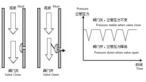
Figure 3 Negative Pulse Ways mud job principle diagram.
2.2 The transmission of electromagnetic waves
Electromagnetic signal transmission relys on stratum medium to achieve . Downhole instruments load the data into the carrier signal, the measurement signal transmit to the surrounding with the carrier signal from the electromagnetic launch, shown in Figure 4, on the ground, ground-based detector uninstall and decode, calculate electromagnetic signals detected ,getting the actual measurement data.
The advantage of this approach are: data transfer speed, suitable for ordinary mud, foam slurry, air drilling, laser drilling, such as directional drilling construction and geological data transmission parameters.
The disadvantage are: formation medium has a greater impact on signals, electromagnetic waves of low-resistivity formation can not pass through, the electromagnetic wave transmission distance is limited, not suitable for deep well construction.
2.3 Acoustic Transmission
To transmit acoustic or seismic signals through the drill pipe is an alternative transfer method. Acoustic telemetry can significantly improve data transfer rate, so that data transfer rate while drilling rise to an order of magnitude , 100bps. Like electromagnetic telemetry , acoustic telemetry don’t need to cycle through the mud, the system uses sound propagation mechanism to work. When the drill pipe, drill bit interact with the bottom, longitudinal elastic wave will appear in the drill pipe. the main parameters of the rocks which can be monitored are rotary frequency of broken instrument, the main is harmonic vibration wave of gear wheel . Vibration amplitude and frequency are related to the extent of wear roller , so we are able to estimate the status of the instrument. When drilling a point of order remain unchanged, the signal amplitude change can also reflect the mechanical properties of rocks. Because spreaded signal attenuation in drill column is very quickly, relay stations need to be installed in the drill pipe column every 400 ~ 500m . The disadvantage of acoustic channel are : less information transmission, low-intensity signal generated at borehole and acoustic noise signal generated by the drilling equipment make very difficult to detect signal, signal attenuation is fast with depth .
2.4 Optical telemetry
Sandia National Laboratories of United States has successfully developed and tested for fiber-optic MWD telemetry systems. The fiber optic cable is very thin and small, low cost, used in a short-term, and finally was washed away and wear out at the drilling mud. Tests of American natural gas Institute, optical depth is able to reach 915M. Fiber-optic telemetry transmit data at a speed of around 1M bps, five orders of magnitude faster than other remote commercial-while-drilling .